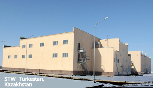
Sewage treatment works (capacity 5000 m3/day)
Characteristics of the incoming waste water:
-BOD 350 mg O2/l.
-Suspended solids 300 mg/liter.
-Phosphate 15 mg/liter.
-Ammonium-nitrogen up to 40 mg/liter.

1-PC fine mechanical treatment grid, 2-sand catcher, 3-installation for air disinfection, 4-mixing chamber, 5-CW circulation pump, 6-bioreactor circulation pump; 7-irrigation system; 8-loading biofilters, 9-aeration zone ; 10-sediment zone; 11-aeration columns, 12-bioreactors, 13-water disinfection unit 14-filter-press, 15-sand and sediment tanks, 16 installations for reagents mixing and dosing, 17-sludge thickeners
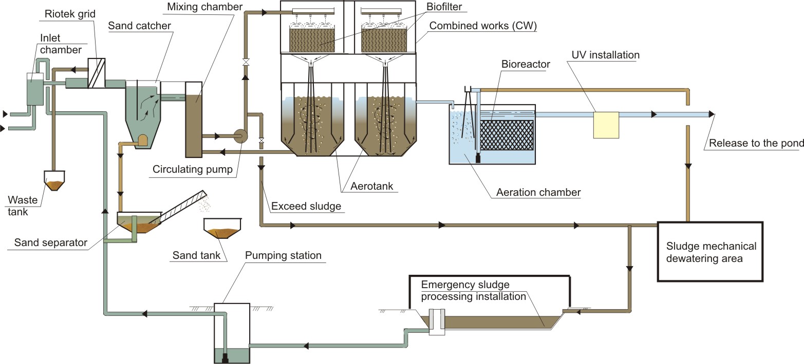
Wastewater (picture 3) is fed into the sewage pumping station, from where it is sent to receiving chamber of sewage treatment facilities block and then is discharged to the step-like fine mechanical treatment grids (with filtering bar spaces-2 mm). Delayed waste is discharged into the storage tank. Waste is removed by trucks to the dump. Having passed through the grids, wastewater is sent to the vertical sand catchers. Sinking sand is pumped into a separator (screw separator), where sand sedimentation takes place. Then, with the help of screw, sand is dumped into sand tanks. Dewatered sand is periodically transported to the landfill. Next sewage is sent to CW mixing chamber consisting of 4 sections. Each section includes biofilter with in-loading and aerotank. CW section are combined into a single technological device with common mixing chamber, circulating pumps and industrial piping.
In the mixing chamber sewage mixes with the circulating sludge mixture from aerotank. The mixture is then fed into biofilter irrigation system with the help of circulating pump. Irrigation system consists of water-distributing trays with discharge pipes and reflective discs. Falling liquid jets break up on discs and irrigate the biofilter loading. Sheets with the waves are set perpendicular to the streams of flowing fluid. Sorption and oxidation of 60 - 70% of organic impurities takes place in biofilter.
Liquid, having passed through the biofilter, is sent to aeration columns, where air entrainment takes place (0,5-0,6 m3/m3) because of vortex funnels appearing. Air-water mixture is distributed by aeration columns over the volume of the aeration basin. Air-water flows impulses on the bottom, emerging bubbles and the movement of gas-liquid flows provide efficient aeration zones mixing. From the aeration zone sludge mixture enters the sediment zone, where it is split. The treated water enters the prefabricated trays and is discharged for further processing, and sludge is grouped into flakes and returns to the aeration zone.
At the same time layer with high concentration of sludge appears in the bottom of sedimentation zone (suspended filter). It ensures wastewater post-treatment and small particles of impurities and sludge retention. Then oxidation of the rest of the organic contaminants (30-40%) occurs.
Biomass (biofilm and activated sludge) in combined works operates on a full oxidation (at a low rate of oxidation and loads on sludge).
Next, purified water is directed into ultraviolet disinfection installations.
Then water entered aerobic bioreactor for post-treatment. Aerobic bioreactor consists of aeration chambers and the reactor with an artificial load. In aerated chamber water is saturated with atmospheric oxygen, necessary for water purification processes with the help of water jet aeration.
Water aeration and mixing in the chambers is carried out by the circulation pumps and aeration columns. The same pumps are used for sediment removal.
From the aeration chambers, water flows into reactors with an artificial load.
Characteristics of residual contamination after purification will be:
-BOD 3-5 mg/liter.
-Suspended solids 3 mg/liter.
-Ammonium-nitrogen 0,5-1,0 mg/liter.
-Phosphorus-phosphate 1,5 mg/liter.
To reduce the phosphorus level up to 0,2 mg/L coagulant dosing into CW or bioreactors is foreseen.
Next, purified water is directed into ultraviolet disinfection installations.
Then purified water is sent to the reservoir.
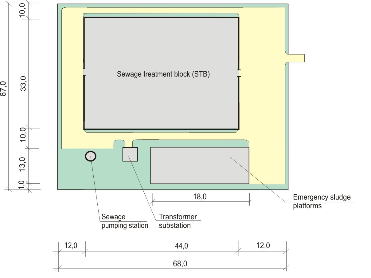
The main technological facilities of STB (combined works and bioreactors) are made of 4 sections, which allows the exploitation of structures in the range from 1250 to 5000 m3/day. Excess activated sludge is sent to sludge thickener, from where it is directed to filter presses for dewatering. Dewatered sludge is discharged to landfill. Emergency sludge platforms are carried out as underground reinforced concrete containers with vertical drainage devices, ventilation and heating systems (for winter time). To intensify the process of dewatering, solution of cationic flocculant is dosed into excess sludge fed into the sludge treatment constructions.
To reduce the zone of sanitary protection up to 100-150 m STB and sludge treatment facilities are equipped with used air processing installation.
Personnel
For normal exploitation of treatment facilities the following number of staff is required.
| # | Description | Number of staff per max shifh |
Number of staff per day |
| 1. | Chief technologist | 1 | 1 |
| 2. | Operators of wastewater treatment | 2 | 4 |
| 3. | Chemical engineer | 1 | 1 |
| 4. | Assistant | 1 | 1 |
| 5. | Cleaners | 1 | 1 |
| total | 6 | 8 |
Technical-and-economic indexes
Capacity of sewage treatment works is 5000 m3/day.
The area of sewage treatment works-0,5 ha.
Electric power required for technological needs of 80 kWh
Justification of the proposed technology
For the construction of sewage treatment plants we propose a technology that has undergone all stages of testing and is recommended by GOSSTROY of RUSSIA.
Environmental reliability is provided by the following factors:
-At intervals in CW functioning, rapid restoration of active microflora in the aeration basin occurs due to the long-term vitality preservation in biofilter (two days and more). In existing aeration facilities while stoppage of work for more than 3 hours active microflora restoring takes 2-3 weeks.
-Repeated circulation of air through the biofilter and aerotank provides preservation and even increasing of treated water temperatures at 1-2oC, whereas in the aeration basins of extended aeration it falls in winter at 2-4oC that leads to the cessation of biochemical processes.
-As the main electromechanical equipment reliable low pressure pumps with a speed of 740-960 rpm with automatic switching and stoppages are used in our structures, while in the existing aeration facilities sophisticated compressors with speed 2900 rpm and manual switching are used.
-Each treatment facilities unit is made of 4 independent sections. It allows switching off one of the sections for repairing for example without reducing the quality of cleaning.
-CW section are ideal-mixing reactors: waste water initially mixes with activated sludge in the mixing chamber, and then contacts with biofilter biocoenosis. Next it is introduced into aeration zone, and finally filtered through a layer of floating sludge that eliminates untreated wastewater slippage and provides high quality of cleaning.
Completion of a closed block of mechanical and biological treatment with local suction devices and installations for disinfection, deodorization and decontamination can reduce the size of the sanitary protection zone up to 100 m.
Reliability and automation of technological mode allows reducing the number of staff up to 8 people.
Reducing energy consumption by 2 times. Power consumed by treatment facilities with pneumatic aeration system with similar oxidizing capaity is 200 kWh. Power consumption of the proposed buildings is 80 kWh
Drainage and dewatering of sand technology is tested at sewage treatment construction in Rostov-on-Don (Voenved district) Q = 12 thousand m3/day.